Take the side-view mirrors as an example. The main aluminum housing has a recessed ledge or seat around the sides on which the mirror sits, originally protected by cork tape padding to avoid glass-on-metal. Over the perimeter of the mirror fits a rectangular aluminum bezel about 3/4" wide through which 8 oval-headed Phillips screws hold it down and are tightened into threaded holes in the main housing.

In the one above, while two screws came out the normal way, six did not. Some of those heads were gone and those with heads, I drilled a hole down the middle, as best I could. Below is one of them; while some may unerringly drill exactly down the middle, I'm not there yet.

Some or all of the remaining screw heads in the bezel can be twisted out with a screwdriver since there's typically not much left holding it on.

Once every hole with something in it is drilled, using a cobalt bit marked with masking tape to the thickness of the bezel to avoid going too deep, the bezel still just doesn't pop off. Unless you can drill out exactly every piece of the former fastener, that won't happen. But if you can find an opening between the bezel and the body, you're in luck.

By very carefully tapping the screwdriver in either direction, the now-weakened fasteners will eventually give way. You'll have to do this around the perimeter and eventually the bezel will pop off.

Then the mirror can be carefully pried up from the housing. In this one, there was a white putty-like substance under the mirror perimeter, cushioning it from direct metal contact and also holding it in place.

After cleaning up the housing comes the fun part. Unless you manage to drill out the entire body of the screw, you will have 'castings' from the remaining screw bodies like the one below.

These, of course, have to be removed and that's done nicely with a Dremel tool and cutting disk.

Grinding at the base of the 'casting,' it doesn't take long to get it off and relatively flush. This one is about ready to come off.

Here's where you see how close you got when drilling out the screw to the bulk of it in the threaded portion of the housing. I didn't do too well on this one - about a 50/50 gap.

You don't want to just keep drilling the hole to the proper depth in the aluminum. First, the bezel screw holes won't line up. Plus, you don't want to remove any more of the original material in the housing if you don't have to.
Using a cobalt bit in one of the good holes, you can determine how far the bit should go in when drilling out the others. A piece of tape on the bit will show you when to stop.


Using the small hole in the aluminum as the staring point, I drill slowly at a 45-degree angle into the remaining faster body, rotating the drill to straight up and down when it's in the screw metal. You end up with something like this.

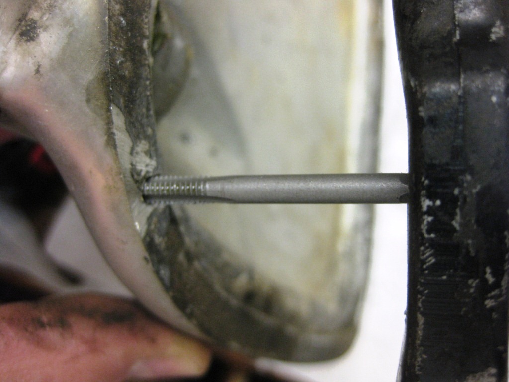
Carefully threading the new hole with an 8-32 tap, you end up almost as good as new.